Why is it so important to try to keep up with the innovation trends? In one word: Productivity. It’s no secret that the number of new structural engineers and students in technical universities is declining. Unfortunately, the number is expected to decrease rather than increase in the future.
Meanwhile, development and design demands, faster construction in developing countries, housing needs, and the push for cost or environmental optimization drive the need for shorter project timelines. With fewer people and more work, increased productivity becomes essential.
Luckily, technology enables us to meet these demands, allowing us to complete designs in minutes that would otherwise take longer with traditional methods.
The real question is: what are our options? Honestly, there are many. It’s almost enough to drive someone mad! The key is understanding them, and the first step is even to know what’s available on the market. IDEA StatiCa offers several options to design connections with just a few clicks. Some have been around for a while, while others, like parametric templates and the automatic design of welds and bolts using machine learning (AI), have been introduced only recently in the latest IDEA StatiCa v24.0. Let’s get straight into this and take a closer look.
Parameters in IDEA StatiCa and Parametric Templates
I will focus on the parameters that can be set directly in IDEA StatiCa and the parametric templates as they are my absolute favorite. The great thing is that both very experienced professionals and juniors can benefit from them.
Practically anyone can activate the developer mode/tab in IDEA StatiCa Connection. Here, you can set parameters that can be linked to specific components based on your specified logic. So, when you modify one component, the other linked elements automatically adjust accordingly.

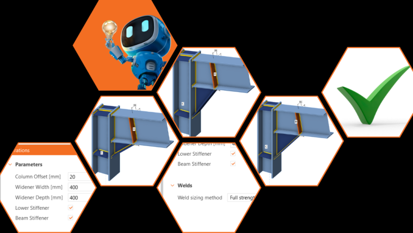
For example, see the figure below. I can specify that if the widener width changes, the position of the stiffeners also changes according to my presets. The same with all the welds, etc. This way, I can interconnect multiple properties, saving me significant time by avoiding repetitive manual adjustments whenever a modification is needed.

In version 24.0, we have taken these parameters a little further. We’ve introduced parametric templates to the Connection Library, accessible within the application. Now, not only can you utilize the existing templates and use them for matching topologies, but you can also explore their settings when creating your own connections. Naturally, you can save the templates you customize for further use or share them with others in your company.

I’ll try to throw in some possible workflow examples where I find using parametric templates most useful and you can benefit from this feature.
- You are dealing with a complex structure (airport hall, stadium, or anything else) where the topology of connections is repeated in one project. Instead of redoing the same operations each time, you can define a single template that you can reuse. Then, you adjust each parameter in the Design section through straightforward inputs.
- As a senior engineer overseeing a junior colleague, you aim to maintain full control over the model while also ensuring efficient verification of the remaining connections. You’ll initially create a model that you’re confident in. Then, your junior colleague can adjust the dimensions without altering the model itself, avoiding the need for additional operations.
Automatic design of the components
From now on, you can forget about designing weld by weld. How would you like just to click a button, and sizes are automatically designed? In IDEA StatiCa, we have several options for welds, but also something for bolts.
Welds can be designed automatically according to capacity estimation or the strength of connected plates (ductility level), depending on which option you choose.
The weld design according to ductility level is calculated according to formulas from the standards. The main inputs here are the thickness and material of the connecting plates, from which the values for the welds are then determined. There are three levels of ductility that you can choose: Minimum Ductility/Full-Strength/Overstrength

In short, it’s all about what you expect from the weld behavior and where you want to use it. Designing for minimum ductility ensures that brittle fracture does not occur while still allowing plastification within the weld (the weld still fails first). The second option (full-strength) produces a thicker weld, and in practice, it means that the resistance of the weld is higher than the plate (plastification of the plate occurs first). The overstrength weld sizing algorithm results in even thicker welds, making the welds significantly stronger than the connected plate. The goal is to enhance safety in plastic design approaches and for cyclic loading scenarios, such as seismic loads.
In addition to the option above, there is the weld design according to capacity estimation. And that’s THE innovation.

The future is here
As you can see, there are numerous ways to enhance your workflow. With increasing pressure on productivity, we are also trying features that can help speed up your designs. I suggest trying them out individually, adjusting based on the specific designs you’re working on. While it might initially feel overwhelming, the benefits of these new options will soon outweigh any initial challenges.