“KG Constructions” experience and advanced BIM technologies: the way to leadership

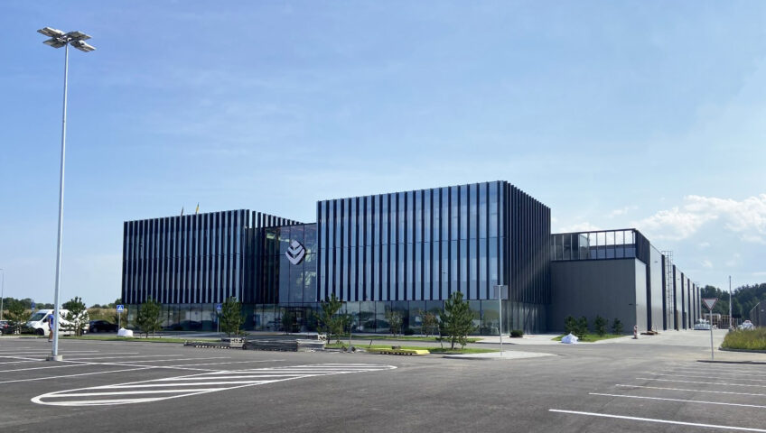
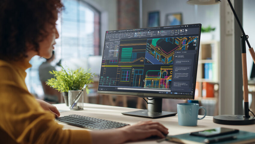
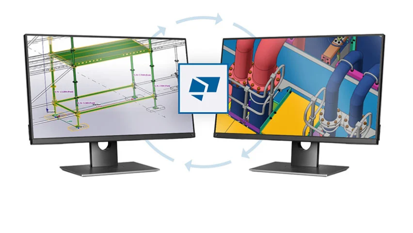
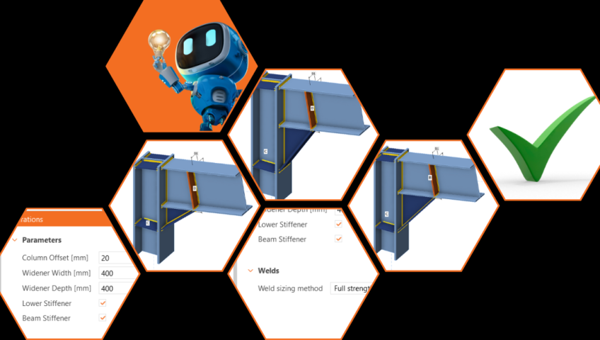
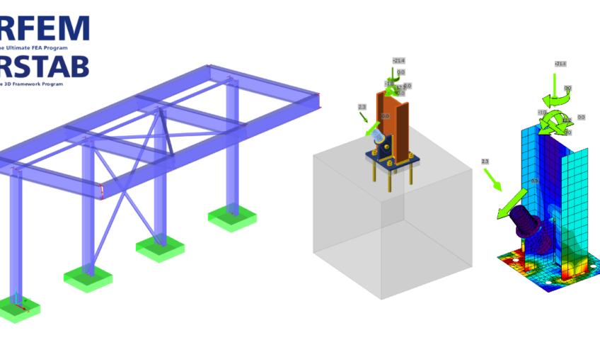
The Lithuanian group of companies KG constructions (kgcgroup.com) is one of the strongest representatives of the facade aluminum and glass construction industry in Northern Europe, which is trusted by the world's most famous architects and the largest construction contractors. Over the years, experience in creating building facades and managing large-scale projects in all its life cycles - from the developing of design tasks and building operation on the construction site - allowed the organization to become a leader and dictate the latest trends in facades industry. Company specialists tell how BIM helps to optimize the time spent on structural design and improve the quality of buildings.               Julius Zykus “KG Constructions” Head of BIM department   Paulius Eigertas “KG Constructions” Structural Engineer The benefits of BIM are understood by all participants in the construction process The most advanced technologies in production and design and the efforts of highly qualified employees have opened wide possibilities for the realization of unique architectural buildings for KG Constructions Group. The head of the company's BIM department, Julius Zykus, does not doubt the benefits of BIM - he is already convinced that BIM ensures better project results.Not only a motivated team is important for effective construction design, but also modern software tools. Therefore, from the beginning of the KG business, investments are made in software technologies that increase work efficiency.   “During our business journey, we can see trends that employees prefer to work with 3D, due to easier to understand visual information. Also desire by clients and architects to see the general picture of the building and how the facade solution will look like in reality in early stages of the project” - says Julius Zykus   Although the company's employees enjoy working with advanced technologies, the main benefit that comes from BIM is for the customer.BIM helps to notice whether all parts of the building will be implemented, whether something has been omitted, such as e.g. wall, which according to known obligations does not belong to any subcontractor. Then a lot of discussions can arise, which stop construction  processes.   “The BIM tools and methods used in the "KG Constructions" group of companies help not only to get new orders, but also to keep the existing ones, since the facades have a lot of detailed and complex solutions, it is not always easy to understand them from technical 2D drawings, and in this place BIM comes to the rescue. This is a help for everyone to fully understand how the facade systems will be installed and what kind of visual picture we will get at the end of the project," - says Julius Zykus.   However, the BIM manager observes a disturbing trend that the choice of software is increasingly becoming a more difficult task. Due to the tendency to work more and more with 3D, the functionality offered by the software is also increasing, but there are many cases that the software is made only for advertising purposes and can only perform specific tasks, but not fulfill all the needs of manufacturing companies or, on the contrary, cannot fulfill the international norms related to BIM requirements, details and amount of information. “Dlubal RFEM 6” software ensures faster and more accurate results   To ensure the quality of its projects, "KG Constructions" has been using the software "Dlubal RFEM 6" for more than two years, which is used to implement practically all projects not only in Lithuania, but also in countries such as Sweden, Denmark, Norway, Finland. According to Paulius Eigerts, head of the static calculation engineer team at “KG Constructions”, the team was looking for a software package that was as suitable as possible for aluminum structures, so when choosing the software, the ability to conveniently create thin-walled cross-sections was particularly very important.   Find out more about Dlubal RFEM 6 on BIMsolutions.ge "While we were starting to work, Dlubal "Knowledge Base" - webinars helped us. At the beginning, we compared the results with other calculation programs, analytical calculations. After half a year, we began to feel confident enough with the results and applied methods. Of course, even today we discover something new and what can speed up the work being done, get more accurate results" - Paulius Eigertas   The essential advantages of the software, which are listed by Paulius, head of the static calculation engineer team: More orderly workflow and processes between other engineer-designers. The Dlubal Center, where we store and exchange system profiles and calculation models created by ourselves, especially contributed to this. Convenient user interface, result and model export - import options, which we miss in other software packages. Abundance of standard documents, calculation methodology and formulas presentation in the results. Program updates are frequent With the added additional add-in with one software package, we can perform almost all the static calculations required for the constructions we are designing. One minor shortcoming faced by company specialists is the not very convenient creation of a calculation reports.   Wooden construction building in Denmark "Marmormolen" Production and installation work by "KG Constructions" in ONE of the LARGEST 28,000 m2 modern wooden construction buildings in Denmark, built using solid wood. In this project, the professional team of "KG Constructions" is responsible for 10,788 m2 of elemental facade with metallic sheet finish, 1550 m2 of PREFABRICATED FACADE WITH ASH add-on SYSTEM AND GLUED LAMINATED WOOD AND 253 m2 of glass roof.   According to Paulius, the biggest challenge in this project was the wooden structure, which makes it difficult to coordinate the harmonious movement of the building during the exhibition between different structures. Software "DLUBAL RFEM 6" was used to perform static system profile, sheet metal calculations, as well as individual component 2D and 3D analysis.   "The biggest benefit of using Dlubal RFEM 6 is the user-friendly environment, the program has a database with different parts of the country” - says Paulius Eigertas

Read more

Power Your Productivity With AI and More: Introducing AutoCAD 2025

If you’re ready to access the latest AI and drafting capabilities that AutoCAD has to offer, open the Autodesk Access application to start your update. On behalf of the entire Autodesk team, welcome to AutoCAD 2025: https://youtu.be/6e1S0rDtr-k “Autodesk is committed to creating the most performant CAD tool in the market. In AutoCAD 2025, you’ll be able to open 2D files up to two times faster than in 2024*,” said Marcus O’Brien, Vice President of AutoCAD. For architecture, engineering, and construction firms, AutoCAD 2025 will deliver deeper connections across the Autodesk portfolio. “When AutoCAD customers use Autodesk Docs, they’ll be able to take advantage of a truly connected experience in the cloud,” said Dania El Hassan, Director of AutoCAD Product Management. “Using Markup Import, customers can share their PDF files in Docs for feedback and instantly see those markups in AutoCAD, making design iterations faster across geographically distributed teams.” AutoCAD 2025 also enhances your 2D and 3D design experience with features that continue to unlock insights and automation with the help of Autodesk AI. “I’m proud that we are accelerating customers’ work with powerful AI for the CAD industry,” said El Hassan. “By targeting the most used workflows, AutoCAD enables customers to focus on their most creative work, leading to better outcomes and leading the CAD industry in the age of AI.” Keep reading to learn more about some of the latest capabilities in AutoCAD 2025. Smart Blocks First introduced in AutoCAD 2024 with the Placement and Replacement features, Smart Blocks represents just one of the ways AutoCAD continues to leverage Autodesk AI to improve the core 2D drafting experience. AutoCAD 2025 now introduces two new capabilities that will help you improve design efficiency through content reuse and standardization across your drawings. “The new Smart Blocks features we’ve released in AutoCAD 2025 represent our commitment to innovation and delivering value to our customers,” said El Hassan. Use Smart Blocks: Search and Convert to quickly organize geometry into blocks. This tool enables you to search drawings by selecting geometry and highlighting all matching objects found on the canvas, providing options to convert them into instances of a block with the help of Autodesk AI. https://youtu.be/OgldCW_dWpg “Search and Convert allows for a more efficient workflow within AutoCAD. Blocks can get lost or be challenging to work with, and this feature allows for a more efficient approach, saving time and quickly creating new blocks from elements within the drawing.” —Joe VanderPluym, Design Associate And with the new Smart Blocks: Object Detection Tech Preview, you can scan drawings for objects to convert into blocks. This tool is designed to help you save time when cleaning up drawings that have been drafted without the use of blocks, created with non-AutoCAD-based applications, or imported from other file formats like PDF. “We’re excited to release Object Detection as a Tech Preview in AutoCAD 2025,” said Britta Ritter Armour, Senior Product Manager, AutoCAD data and AI. “It’s a new type of feature that allows us to enhance capabilities throughout the year, without requiring users to update.” https://youtu.be/evtw8-pfI2Q Autodesk Assistant First introduced in the AutoCAD and AutoCAD LT 2024.1 update, Autodesk Assistant gives customers quick access to help resources using the built-in palette. With AutoCAD 2025, Autodesk Assistant is now enhanced with Autodesk AI for a conversational interface that provides generative responses. https://youtu.be/-CpRyyqL1o0 “Previously, I had always used other tools for seeking information, but then you always need to specify much more if you want to find something that works for your specific problem. The Autodesk Assistant actually gives me the correct commands directly in the reply, exactly what I would need from an AI assistant.” —Markus Karlsson, Senior Designer, Shipbuilding Enhancements for Projects on Autodesk Docs AutoCAD 2025 introduces several enhancements for customers who manage design projects using Autodesk Docs—our cloud-based common data environment available with the AEC Collection. With Markup Import, you can now connect PDF files with markups made in Autodesk Docs into AutoCAD to continuously synchronize changes made by collaborators using the full set of markup tools available in Docs. https://youtu.be/AA-Bs5_olq4 In AutoCAD 2025, Activity Insights has been enhanced to include detailed event properties and the ability to filter by DWG version with robust file comparison capabilities—merging features from the previous DWG History tool—to create one source for exploring all drawing changes over the course of a design. Versioning is now supported for drawings managed on Autodesk Docs, requiring no additional setup or configuration to view Activity Insights. Start tracking over 35 activity types that can be viewed using Activity Insights palette or directly from the AutoCAD Start Tab—without requiring you to open drawings. ArcGIS® Basemaps Ground your projects with real-world geographical information using Esri’s ArcGIS® Basemaps, now available directly in AutoCAD 2025. Access five Basemaps in the form of high-resolution satellite and aerial imagery, OpenStreetMaps and Streets, along with light and dark gray monochrome map styles, providing architects, engineers, and construction professionals with the foundations to make informed decisions.   Source: www.autodesk.com

Read more

Beyond steel and concrete: How multiple design disciplines are using Tekla Structures as a platform

Respected by BIM designers the world over, Tekla Structures is increasingly being used as a platform to create specialized tools for specific construction tasks. Tekla’s open API makes this easier than developers may realize. The heart of South Africa’s rich mining industry is the province of Gauteng. Here more than 150 mines produce around a quarter of the country’s minerals. Most of it is gold, extracted from vast underground deposits and processed on the surface in specialized plants. Self-taught BIM expert Marhinus du Plessis has been designing these mineral-processing plants for his entire career. Early on he spotted opportunities to improve the efficiency of plant design – especially the piping – by using BIM tools in non-traditional ways. “Piping was always done in a separate platform. But then I realized we could bring the piping design into Tekla Structures and automate the entire process with just a few parameters. So I started using the Tekla API to design an add-on myself,” he says. Fast forward several years and du Plessis is Managing Director of a company he co-founded: ParaMatic. His team has developed a BIM solution of the same name specifically for Mechanical, Electrical and Plumbing (MEP) design. It’s built on top of Tekla Structures. In addition to South Africa, the company has mineral-processing customers in Australia, Turkey and the United States. “I’ve used about 10 different CAD or engineering systems during my career. Tekla Structures was always the one that could do more than in the rest. With ParaMatic you can perform tasks in under two minutes that can take hundreds of hours with traditional tools,” says du Plessis. “I like the fact that Tekla Structures is a database-driven platform where you can assign as many attributes as you want to an object. Then you can use these attributes in various applications – from creating 2D drawings to running reports.” “It’s also extremely robust. I’ve seen teams of 40 people waste hundreds of hours when unstable platforms crash. Not so with Tekla Structures,” he adds. Access the code, check the calculations ParaMatic is representative of the growing recognition Tekla Structures is gaining outside of its traditional use for steel and concrete design. Thanks to its open API, other industries requiring specialized construction can easily customize the software. ScaffPlan is an Australian company that has built an end-to-end scaffolding solution on top of Tekla Structures. It’s now used by customers around the world and has completely transformed the industry for scaffolding design and construction. “When we got started, we did proof of concepts with three different platforms to see which was the most suitable. Tekla was by far the best option. It’s so easy and flexible to work with,” says Simon Boyes, the Founder and CEO of ScaffPlan. Boyes started out as a scaffold yard laborer and worked his way up to running some of the industry’s most complex projects. ScaffPlan was created to make work faster, more cost-efficient and safer. “We’ve drawn everything in 3D that scaffolders need. But we’ve also written the code in the background, so engineers can perform calculation checks to make sure designs are safe and strong enough,” he explains. Pawel Lisowski is ScaffPlan’s Head of Software Development. Another self-taught BIM developer, Lisowoski says complete constructability is what sets Tekla apart from other BIM solutions. “With Tekla, what you see in the model is what you get on site. No other software can offer constructability to this level of detail,” he explains. “Thanks to the open API, a developer can talk to Tekla Structures through the code. You have access to all the data behind what you’re modeling. This means you can easily create your desired output, as all the information is there.” “It’s really easy too – you do not need a background in computer science,” says Lisowski. Open to any type of construction Tekla Structures can be used to model components of standard shapes and sizes, as well as to create custom-fabricated building materials and products. The development team from ParaMatic has been using the open API to bring their customers’ component catalogs into the system. “We have an online database where the dimensions of all the objects are listed. Our code then reads that information and draws it into Tekla. This allows us to easily bring in more catalogs. We don’t need to model anything manually – it’s all automatically generated by the code,” says ParaMatic Systems Design Engineer, Francois De Jager. “Another reason we like Tekla is because the integration between their products is very good. Our draftsmen use Trimble Connect to access the model onsite and make any changes that need doing. Everything is immediately and seamlessly updated without the need to import and export IFC files,” says De Jager. Both ParaMatic and ScaffPlan are now looking to expand the use of their Tekla-based platforms to support adjacent use cases. ParaMatic is adding specific functionality for handling fire reticulation, plumbing and wastewater. Cable racking and ducting are also in the roadmap. ScaffPlan is developing its software to cover formwork, shoring and other temporary works. “There's no limitation to what you can do through the API. It doesn’t matter what type of construction you’re designing for – it can be done in Tekla,” says ParaMatic Managing Director Marhinus du Plessis.   Article from Tekla.com

Read more

Challenges of the 5D BIM implementation

The construction project, in general, is a product of defined quality built within an optimal time frame using available resources as in any other industry, so its success depends on controlling the costs during the execution period (schedule). Considering the usual dynamics of construction projects, the latest tendencies suggest that the best way to control and plan these processes is to do it in an integrated way. This could be achieved through LEAN project planning and 5D BIM analyses, but achieving it is often a complex and time-consuming process. It requires all steps from the early design phase to execution to be strictly pre-defined, heavily modified and coordinated. It often implies adopting a certain standardized system, which has to be implemented by all stakeholders, and that often proves difficult. Project planning and cost management are generally complex tasks, and integrating them into 5D simulation, even with the most modern software tools, is challenging and requires a huge amount of data and working hours to execute properly. So, in short, we know the right way of doing things but don’t have the proper tools to achieve set goals with reasonable resources. As a result of this imbalance between aspirations and capabilities, productivity rates in our industry have stagnated for decades and are seriously falling behind other industries. It seems like construction is unable to utilize the advantages of technology development like in other sectors and still heavily relies on costly, time-consuming manual processes and low levels of automation, especially within the planning and organization processes. Digitalization in construction only brings new digital tools, but as of now, processes still need to be more efficient than before. The next generation of project management Widespread implementation of BIM (Building Information Modeling) and successful adoption of common construction logic by most authoring construction software tools, as well as the immense contribution of professional associations like building SMART International in standardization and interoperability of processes within BIM, allowed us to develop whole new project management concepts. We can now base project organization on general premises without the need to fully implement a specific standardized system. The idea is to allow project managers to create integrated 5D simulations without the need to significantly predefine information integrated into the central BIM model and to rely mostly on available data and common construction logic widely accepted within the industry. Using the BEXEL Manager software suite, this could be achieved in an incredibly short time with a handful of resources and five general steps described below. Step 1: Automatic Quantity Takeoff generation In order to simplify the process of quantity control and WBS (Work Breakdown Structure) creation and yet keep it detailed enough to give us the needed level of control, we need to adopt and use information from previous project phases since requiring substantial modification of previous phases implicates re-work, and often demotivates team for BIM implementation. If we analyze WBS and QTO (Quantity Takeoff), we can notice that their structure relies on some basic principles that are pretty intuitive and commonly accepted within the industry regardless of market and type of construction project. Works are generally separated into four main groups (Structural works, Architectural works, MEP and Landscape and roads) simply because design work is separated by disciplines, and the following project phases just follow that logic. Building elements are then sorted by their function or type, and this logic is also followed in software authoring tools with IFC types or element categories (foundations, walls, slabs, columns, windows, conduits, etc.), which give an additional level of organization. At the lowest level of organization, project elements are sorted by materials and detailed parameters defined by designers. Suppose we translate this logic into a BIM environment. In that case, design work is separated by disciplines, with different sources of central federated BIM model, model elements are organized in specific categories (IFC types) within the authoring tool, and at the lowest level of organization, elements are categorized in families defined by designers. So, the logical organizational structure for QTO on the project could be based on these existing parameters with no need for full implementation of specific standardization or coding system. We just need a proper software tool to allow us to utilize these general parameters. Step 2: Smart Cost Classification creation and adjustments Similar to the traditional process, after developing QTO, the next step is to develop a cost database. BEXEL Manager platform allows the further use of created QTO as a WBS basis to automatically generate Cost Classification, with a structure that follows the described general organization based on available data. The created Cost structure could be adjusted and fine-tuned to a certain level, but practically 90% of the project cost structure is defined automatically without the need for additional information or a standardization system. Such an approach gives the user the opportunity to create and enrich its own properly structured Cost Classification adding cost and resources information to automatically created database and re-use it in future projects. Step 3: Auto-assign process and linking cost items with model elements Since the QTO (WBS) structure and Cost Classification based on it are created and fine-tuned, the user is able to initiate the Auto-assign process, which links newly created cost items with actual BIM model elements. With the set of automatically created rules, a smart cost management engine links model elements to appropriate cost items. Based on existing parameters, a smart computer engine creates element queries (rules) that link Cost Items defined in Cost Classification with corresponding model elements. In this way, all future changes and updates of the project will be automatically reflected in the cost structure. Step 4: Defining inputs for automatic schedule creation Defining the construction schedule or 4th dimension (time) of the project might be even more challenging than the 5th (cost information). The project manager has to take into account construction process technology, organization of the construction site, contractor’s resources, and time frame defined by the investor. When it comes to construction planning, we can say that we have good practices and a vast knowledge base, we have BIM, and we have great project planning methods (LOB, flow-line schedule), but the amount of data and number of engineer hours needed for proper implementation are still incredibly high. Therefore, the general approach to scheduling is usually simplified, which leads to a significant reduction in precision and bad project performance. In order to overcome these obstacles, we have to turn on advancements in computing technology, capture expert logic, and utilize it through IT. We have to combine the knowledge, experience, and creativity of planning professionals with massive computing power and big data management and adopt the “human-machine teaming” concept into project scheduling in order to make it more efficient. But what does that mean in practice? It means full automation of repetitive, time-consuming tasks in project planning and giving professionals the opportunity to define the logic and structure of the construction process and leave the actual repetitive process of schedule generation to a computer algorithm. In order to automate the process, first, you need to analyze it and identify patterns upon which the process is based. Construction planning, in general, represents the organization of works, or to simplify it, the spatial distribution of works (labelled Creation Zones in software) and construction work sequence (defined as Creation Methodology). Spatial distribution of works (Creation Zones) is something that could be considered as a universally adopted principle in construction. Every construction project in the world is “divided” into smaller organizational units. In the classic scheduling process, it is necessary to recreate this logical organization over and over for every single part of a schedule and to define relations between every single unit. For large-scale projects, this could lead to a gargantuan schedule with a large number of tasks that have to be properly defined and interconnected to work. In reality, project managers often just simplify schedule structure and segregate works into larger groups and larger spatial zones, which, in the end, leads to underdeveloped schedules. But, with BEXEL Manager intelligent scheduling engine, this could be improved. This new way of schedule creation gives the project manager an opportunity to define the principles and logic of the schedule, and final tasks and relations are generated by computer algorithm. Step 5: Automated smart planning and optimization After the previously mentioned elements are defined, the user only has to combine them in a proper sequence (Creation template) and initiate a smart scheduling engine. Based on defined spatial distribution and creation methodology (sequence of works), the computer algorithm automatically generates a construction schedule with a detailed structure and a large number of individual tasks completely integrated with project cost classification and linked to model elements. The created schedule consists of tasks for every activity in every construction phase (zone) on every floor within every building, with relations based on project manager inputs defined in previous steps.

Read more

FIN EC Software

Structural Analysis Structural analysis software for calculation of internal forces and deformations of spatial (Fin 3D) and planar (Fin 2D) truss and frame structures using finite element method. The programs stand out with their simple user interface and easy workflow. In addition to the basic calculation of internal forces and deformations, these programs can be used to solve complex problems (linear stability, dynamic calculations, and calculations according to the 2nd order theory). Structural Design Calculated structures can be verified in fundamental structural design programs or may be checked for fire resistance. The continuity of the FIN programs and the designing programs is simple to use, therefore the user can shift during work seamlessly from one program to another, and the data is always synchronized automatically. Fast and Easy Design Design programs are made for fast designing of structural members under load. The programs emphasize ease of use and detailed output documentation. Programs are available standalone or linked with FEM programs. Wide Range of Supported Materials Programs are available for all of the most commonly used materials in structures. The key programs are Steel, Concrete and Timber. These products perform analysis in compliance with the basic design standards for relevant structures. A unique product is the Concrete Beam program, which is designed for comprehensive analysis of horizontal RC structures, including verification of cracks and deflections. Design programs can also be used as assessment modules for the FEM programs Fin 2D and Fin 3D. Using the variable import of internal forces, the programs can also be used in connection with other structural software. FIN 3D has been developed to performs structural analysis of 3D structures using the Finite Element Method (FEM). The program allows simple entering of structures and contains user-friendly interface to view results of structural analysis. Interaction with designing programs of FIN EC package gives user the advantage of structure verification in these specialized programs and sending the results back to FIN 3D. Main features Various types of members (basic, beam on subsoil, excluded tension/compression) Database of common steel, timber, concrete and masonry cross-sections Generator of most common structures (trusses, frames etc...) including loading Import of structure layout in *.dxf file format Copy of structures or their parts from one project to another Generator of combinations (mutual excluding of selected load states, determination of main variable loads etc...) Analysis according to the theories of 1st and 2nd order Dynamics - calculation of eigenmodes and natural frequencies Linear stability - calculation of critical load Members can be verified in programs Steel, Steel Fire , Timber, Timber Fire, Concrete, Concrete Beam and Concrete Fire Optimization of verification time with the help of design members and design groups Easy printing of well-arranged documents Additional tools Section – Calculation of cross-sectional characteristics of arbitrary shapes Sector – Characteristics of thin-walled steel cross-sections Steel Joints and Column Bases Verification of joints in steel structures can be performed in the Steel Connections program, which enables the design of a wide range of steel joints, ranging from fin and end plates, to truss joints and anchoring steel columns and foundations. The analysis is performed by analytical methods and the program offers detailed documentation of the calculation process. The results are therefore easily verifiable. A joint preview can be saved as a drawing, which can be further edited in CAD programs. Punching of Reinforced Concrete Slabs The program Punching is designed to analyze the punching of a column through a reinforced concrete slab. The program supports various shapes of columns and column heads. Automatic design of shear reinforcement is included in the verification.

Read more

Design connections in just a few clicks!

Why is it so important to try to keep up with the innovation trends? In one word: Productivity. It's no secret that the number of new structural engineers and students in technical universities is declining. Unfortunately, the number is expected to decrease rather than increase in the future. Meanwhile, development and design demands, faster construction in developing countries, housing needs, and the push for cost or environmental optimization drive the need for shorter project timelines. With fewer people and more work, increased productivity becomes essential. Luckily, technology enables us to meet these demands, allowing us to complete designs in minutes that would otherwise take longer with traditional methods. The real question is: what are our options? Honestly, there are many. It's almost enough to drive someone mad! The key is understanding them, and the first step is even to know what's available on the market. IDEA StatiCa offers several options to design connections with just a few clicks. Some have been around for a while, while others, like parametric templates and the automatic design of welds and bolts using machine learning (AI), have been introduced only recently in the latest IDEA StatiCa v24.0. Let's get straight into this and take a closer look. Parameters in IDEA StatiCa and Parametric Templates I will focus on the parameters that can be set directly in IDEA StatiCa and the parametric templates as they are my absolute favorite. The great thing is that both very experienced professionals and juniors can benefit from them. Practically anyone can activate the developer mode/tab in IDEA StatiCa Connection. Here, you can set parameters that can be linked to specific components based on your specified logic. So, when you modify one component, the other linked elements automatically adjust accordingly. For example, see the figure below. I can specify that if the widener width changes, the position of the stiffeners also changes according to my presets. The same with all the welds, etc. This way, I can interconnect multiple properties, saving me significant time by avoiding repetitive manual adjustments whenever a modification is needed. In version 24.0, we have taken these parameters a little further. We've introduced parametric templates to the Connection Library, accessible within the application. Now, not only can you utilize the existing templates and use them for matching topologies, but you can also explore their settings when creating your own connections. Naturally, you can save the templates you customize for further use or share them with others in your company. I'll try to throw in some possible workflow examples where I find using parametric templates most useful and you can benefit from this feature. You are dealing with a complex structure (airport hall, stadium, or anything else) where the topology of connections is repeated in one project. Instead of redoing the same operations each time, you can define a single template that you can reuse. Then, you adjust each parameter in the Design section through straightforward inputs. As a senior engineer overseeing a junior colleague, you aim to maintain full control over the model while also ensuring efficient verification of the remaining connections. You'll initially create a model that you're confident in. Then, your junior colleague can adjust the dimensions without altering the model itself, avoiding the need for additional operations. Automatic design of the components From now on, you can forget about designing weld by weld. How would you like just to click a button, and sizes are automatically designed? In IDEA StatiCa, we have several options for welds, but also something for bolts. Welds can be designed automatically according to capacity estimation or the strength of connected plates (ductility level), depending on which option you choose. The weld design according to ductility level is calculated according to formulas from the standards. The main inputs here are the thickness and material of the connecting plates, from which the values for the welds are then determined. There are three levels of ductility that you can choose: Minimum Ductility/Full-Strength/Overstrength In short, it's all about what you expect from the weld behavior and where you want to use it. Designing for minimum ductility ensures that brittle fracture does not occur while still allowing plastification within the weld (the weld still fails first). The second option (full-strength) produces a thicker weld, and in practice, it means that the resistance of the weld is higher than the plate (plastification of the plate occurs first). The overstrength weld sizing algorithm results in even thicker welds, making the welds significantly stronger than the connected plate. The goal is to enhance safety in plastic design approaches and for cyclic loading scenarios, such as seismic loads. In addition to the option above, there is the weld design according to capacity estimation. And that's THE innovation. The future is here As you can see, there are numerous ways to enhance your workflow. With increasing pressure on productivity, we are also trying features that can help speed up your designs. I suggest trying them out individually, adjusting based on the specific designs you're working on. While it might initially feel overwhelming, the benefits of these new options will soon outweigh any initial challenges.   source: ideastatica.com

Read more

Innovative Structural Analysis & Design Software for Engineers

For more than 30 years, Dlubal Software has developed advanced structural analysis and design software that is popular with structural and civil engineers. The core programs RFEM and RSTAB are used in 132 countries worldwide and impress with high precision, reliability, and user-friendliness. More than 130,000 users rely on the expertise of Dlubal Software. 13,000 companies use our software in their daily tasks. A global network with branch offices in the USA, Germany, China, France, Italy, Poland, and the Czech Republic guarantees optimal service and support. Dlubal provides a reliable basis for your design processes. Since the company foundation in 1987, Dlubal Software has focused on developing intuitive and efficient software solutions for static and dynamic analysis, CFD analysis, and structural design. Dlubal Software Advantages Universal Software One software can provide multiple design solutions Getting started is simple with our online learning resources, training options, and Dlubal support team Modular Structure Purchase the add-ons specific to your design projects Flexible options to rent or buy add-ons at a later time Free Support / Service Over 20 experienced Dlubal engineers providing professional and efficient support Save on paid support: Support via email and chat is also available free of charge Free 24/7 access to online learning such as FAQ, forum, videos, webinars, and more Optional Basic or Pro Service Contract for priority email, phone, and screen sharing support Short Introductory Period No more dealing with lengthy introductory periods: Learn to use the software quickly and efficiently with the intuitive and user-friendly interface Access free online videos, webinars, FAQ, and more to learn at your own pace Internationally Known and Recognized Software Familiarity Familiarity with Dlubal products across universities and companies around the world Maximum acceptance: Tested and reliable results for user assurance Maximum security! Join the over 100,000 users in 95 countries who trust in Dlubal Software Free university and student license access for the next generation engineers Reliable and established company with over 35 years of experience BIM-Compatible Software Direct BIM integration to programs such as Revit, Tekla and AutoCAD Integration to alternative programs with DXF, IFC, SAF, and other file types Free Additional Program Features Automatic wind and snow load generators according to various standards Automatic load combination generators according to various standards Cable, tension only, compression only, and other nonlinear member types 2D surface and 3D solid FEA analysis (RFEM) Multiple languages supported including 11 GUI and 13 printout report language options Efficient cross-program work: BIM data exchange supporting various formats including IFC, DXF, Revit, Tekla, AutoCAD, and many more CFD Wind Simulations and Wind Load Generation Integrate RFEM or RSTAB structures with the stand-alone program RWIND to apply CFD wind simulation in a numerical wind tunnel Determine wind pressures for all structure types including complex and unique geometries Export the generated wind loads from RWIND back to RFEM or RSTAB for the structure design Pushover Analysis: Evaluation of Seismic Resistance Earthquakes have a significant influence on the deformation of structures. The pushover analysis determines precisely their seismic resistance. It accounts for deformations and possible damage by creating a capacity curve that includes the nonlinear properties of a building. The method compares this curve to the expected seismic effects, supported by specialized add-ons and international standards. Results are clearly shown in graphics and tables for easy safety evaluation. Discover our Pushover Analysis software to efficiently evaluate the seismic stability of your projects.

Read more

Benefits of DDScad software

Up to 80% of the total project development cost account for changes to the original design. Moreover, we know that design errors cause significant extra costs in a project. Consequently, we have developed DDS-CAD so that design changes are as simple and error free as possible, which improves project productivity. We also aim to really amaze you with the efficiency of our software when submitting your project updates to other design partners, making the process almost effortless and without any loss of information. Re-entry of data is one of the most common causes of error, and DDS-CAD aims to reduce this to a minimum. It is through listening to our partners, who have been asking for improved data transfer, that we have implemented the buildingSMART/IFC data exchange format as a supported standard in the software, and adopted the “BIM” (Building Information Modeling) concept at a very early stage. DDS-CAD was the first MEP application to introduce IFC support as standard, and has been a market leader in buildingSMART implementation and innovation. What this means in practice is that designing with DDS-CAD goes far beyond simple 2D CAD drafting. With DDS-CAD you develop an intelligent model of the building’s MEP services, and thus the basis of a complete building simulation. Continuous development of DDS-CAD is undertaken to keep the software up to date with new technologies and future developments in the industry. For designers in the construction industry, for example, a challenge they face is the economical transfer of existing building plans, only available in paper form, into intelligent digital models. This is particularly important, as planned renovations to the enormous existing building stock are now required, or will be in the near future. This represents a huge potential for new business for planners and designers. For this reason, DDS-CAD is already equipped with the ability to convert scanned building plans to intelligent building model files in an efficient and productive manner. On this basis, building models developed in DDS-CAD can then be used to plan the renovations of existing buildings in an efficient and cost effective manner. These examples indicate: We are closely keeping an eye on the developments affecting the industry, and respond quickly to a foreseeable need. When this finally occurs, it is already provided by DDS-CAD. Roll-out without interruptions: The DDS implementation Smooth integration into your design processes, ensuring high level of approval In our experience, an average working week of 60 hours or more is not unusual for planners and designers. The introduction of software such as DDS-CAD is always done so in order to simplify planning processes and optimize them to exploit new opportunities, ultimately saving time and therefore reducing costs. This is how we have designed the software. But that is not enough, since experience shows that users welcome and accept new software, if the introduction and implementation of the software is successful. In most engineering companies in which DDS-CAD is introduced, the software is replacing an existing planning program. Our consultants plan such changes carefully, ensuring there is a direct cost-benefit from the introduction of DDS-CAD. In our experience, the implementation of our software in your project work can be done in such a way that ensures that the projects will not be delayed in any way or worse still, stopped. We support our partners step-by-step during the impotant integration of DDS-CAD into your existing daily processes. In this way, the transition from a traditional drafting software to the DDS-CAD BIM solution happens quickly, safely and smoothly. In practice, we frequently take two different approaches. In many offices, a preliminary outline design is done by the engineer, which is then created by a CAD operator before calculations are made. Then the dimensions are assigned and the necessary calculations are carried out by the engineer. The results are then incorporated into. Only a planning solution, which is focused on future requirements, can give you a competitive advantage and investment protection as a user. For that reason the DDS-CAD development team has had the same target for years - not only to meet the current needs of users, but also integrate new technologies into the software. In this way, DDS-CAD users at all times have a software solution available for CAD and BIM design for buildings from a pioneer and innovation leader. This ensures that you use a tool, which is always equal to the demands of practice. To respond quickly to new technologies and changing demands, DDS-CAD has from the beginning been conceived as a standalone solution. In this way, it has its own powerful 3D CAD core and does not rely on a thirdparty CAD engine as a base application. This saves costs and update overheads - with full power and flexibility. A fully integrated DXF/DWG interface provides effortless read/write access to these important traditional document formats. An intelligent and independent DDS-CAD core is equipped with numerous features that are, in principle, available in all the programs. So whether you are an electrical engineer on a electrical module, or use it as a mechanical designer with modules for plumbing, heating, air conditioning and ventilation: the discipline specific features and functions of your software are based on a comprehensive foundation, which alone already offers numerous benefits. In this DDS-CAD core functionality, genuine value is added. Despite its high performance, DDS-CAD requires only minimal demands on your hardware resources. With a standard modern Windows based computer system, and a decent graphics card, you are ideally equipped for DDS-CAD. Your benefit Use of modern and flexible design software from only one company, no extra costs or double update overhead, simple processing of existing plans and information through appropriate interfaces (DWG/DXF, PDF and IFC). Additional expensive hardware investments are not required to use DDS-CAD.   hat’s why DDS-CAD! Quality Plan, calculate, simulate and document building related mechanical, electrical and plumbing systems at the highest quality level. Process Optimization Software that integrates seamlessly and optimizes your workflow. We assure a smooth implementation without disruptions to your daily processes. Compatibility Secure full compatibility with all popular CAD/BIM applications used by architects, structural engineers and contractors. Save Time Achieve an unprecedented project turn-around speed. Intelligent and automated features provide more efficiency, obtaining results faster. Independence Use an independent, stand-alone solution; additional third party CAD programs (such as AutoCAD or Revit) are not required. Resulting in no duplicate purchases, training, update and maintenance costs. BIM Create intelligent systems within an interactive building model, using smart components and objects. Benefit directly from extensive experience of DDS as one of the pioneers in BIM development. In Control Profit from integrated multi-disciplinary control functions such as collision detection, model validity checks, correct object connections, etc. In Control Profit from integrated multi-disciplinary control functions such as collision detection, model validity checks, correct object connections, etc. Integrated Calculations Optimize your system designs by making use of integrated calculations. The intelligent building model provides the requirements and the software will assure your designs will perform accordingly. Minimize Liability Enhance the quality of your deliverables by making use of the integrated expertise on all levels. Avoid planning errors and minimize your liability risks.

Read more

Benefits of Autodesk Revit for Architectural, Structural, and MEP Professionals

Revit is a Building Information Modeling (BIM) software that has revolutionized the construction industry. It is widely used by architects, engineers, contractors, and builders to design, visualize, and simulate building projects. Revit has many benefits for different trades, which we will discuss in this blog. Revit Architecture Revit Architecture is a powerful tool that allows architects to design and visualize buildings in 3D. It enables architects to create accurate and detailed drawings, renderings, and animations of their designs. Revit Architecture has many benefits, including: Improved Accuracy: Revit Architecture allows architects to create accurate and precise designs. They can easily make changes to their designs and see how the changes affect the entire building model. Enhanced Collaboration: Revit Architecture enables architects to collaborate with other team members in real time. It helps in reducing errors and inconsistencies in the design process. Efficient Project Management: Revit Architecture helps architects to manage their projects efficiently. They can easily track project progress, schedule tasks, and manage resources. Revit MEP Revit MEP is a BIM software that is used by mechanical, electrical, and plumbing (MEP) engineers to design and simulate building systems. Revit MEP has many benefits, including: Improved Coordination: Revit MEP enables MEP engineers to coordinate their designs with other trades. It helps in reducing clashes and errors during the construction process. Enhanced Efficiency: Revit MEP allows MEP engineers to create accurate and detailed designs. They can easily make changes to their designs and see how the changes affect the entire building model. Accurate Cost Estimation: Revit MEP helps MEP engineers to estimate the cost of building systems accurately. They can easily calculate the quantity of materials and equipment required for the project. Revit Structure: Revit Structure is a BIM software that is used by structural engineers to design and simulate building structures. Revit Structure has many benefits, including: Improved Accuracy: Revit Structure allows structural engineers to create accurate and precise designs. They can easily make changes to their designs and see how the changes affect the entire building model. Enhanced Collaboration: Revit Structure enables structural engineers to collaborate with other team members in real time. It helps in reducing errors and inconsistencies in the design process. Efficient Project Management: Revit Structure helps structural engineers to manage their projects efficiently. They can easily track project progress, schedule tasks, and manage resources. Autodesk Revit for Various Stages of a Building Life Cycle Revit is the powerful building information modeling (BIM) software used for a variety of purposes in the architecture, engineering, and construction (AEC) industry. Here are some examples of how Revit is used: Revit for the Building Life-cycle | ASC Technology Solutions Building Design: Revit is commonly used for designing buildings and creating 3D models of architectural designs. It allows architects to create detailed building designs, visualize the project in 3D, and produce detailed documentation and construction drawings. Structural Engineering: Revit is also used for structural engineering. It has tools for creating detailed models of structural elements such as beams, columns, and walls. Engineers can use these models to analyze the structural performance of a building and ensure that it meets safety standards. MEP Engineering: Revit is highly beneficial for mechanical, electrical, and plumbing (MEP) engineering. It has tools for designing and modeling complex MEP systems such as HVAC, electrical, and plumbing systems. MEP engineers use these Revit models to ensure that the systems are properly integrated with the building design. Construction Management: Autodesk Revit is highly recommended for construction management. It allows construction managers to visualize the construction process and plan the construction sequence. It is also used to coordinate construction activities and communicate project information to stakeholders. Facility Management: Revit models are used for facility management. The information-rich Revit models are used by the facility manager to manage the maintenance and operations of the building more efficiently. Revit for General Contractors Revit is also widely used by general contractors to estimate costs, plan projects, and manage resources. Revit allows general contractors to plan their projects efficiently, track project progress, and manage resources effectively. Revit also enables general contractors to communicate effectively with other team members, helping to reduce errors and inconsistencies during the construction process. Revit is a powerful BIM tool that has many benefits for architects, general contractors, sub-contractors, estimators, and fabricators. It allows these different trades to design, simulate, and manage building projects efficiently. Revit improves accuracy, enhances collaboration, and streamlines project management. It is an essential tool for anyone involved in the Architectural Engineering and Construction (AEC) industry. source: www.asctechno.com

Read more

BEXEL manager-The experience of the Dominicans

Sensatori & Nickelodeon Hotels and Resorts, Punta Cana Nestled along the stunning coastline of Punta Cana in the Dominican Republic, Sensatori & Nickelodeon Hotels and Resorts, Punta Cana offers a unique blend of luxury and family-friendly entertainment. The resort consists of 460 suites with an adults-only section, decadent honeymoon suites, spacious family suites as well as eight private garden villas. The heart of the resort features The Gourmet Village, showcasing a variety of boutiques, coffee shop, theatre, open-air cinema, wedding plaza, gourmet inclusive bars, lounges and restaurants framed by open-air terraces and reflection pools. BEXEL Manager was used from the early design stages until project completion. Comprehensive design review analyses were performed to thoroughly assess and mitigate any potential risks of changes in the project that may result in additional expenses for the owner. Every planned aspect of the project was executed on time and according to the schedule.   Clash detection reports and metadata checks were performed regularly and shared with stakeholders using BCF (BIM Collaboration Format) in order to ensure high-quality design information. Early identification and resolution of design conflicts reduced the likelihood of costly rework and construction delays and ensured the accuracy and completeness of design information, enhancing overall project quality and performance. The baseline schedule is intelligently linked with BIM model elements and embedded pricing and cost information, enabling 4D/5D simulations. Model-based histograms of materials, labour, and equipment allocation were generated, and resource requirements were quantified and calculated. This further enhanced collaboration across stakeholders, making progress monitoring digitally enabled. 4D Simulations notably increased overall efficiency and workforce organisation on site, up to 70% in some areas. All scheduling and cost data were produced in IFC4 file formats for data sharing. The benefit for the client was the ability to accurately track execution progress and the total cost of executed works. Construction monitoring was done by an onsite monitoring team that collected, analyzed, and processed all construction progress data – while generating daily progress and cost tracking audits, executive reports and schedule impact predictions.

Read more

Dlubal – Structural Analysis and Design Software

Reinforced Concrete Structures Discover the Dlubal structural engineering software for precise analysis and design of concrete structures. RFEM and RSTAB are designed to efficiently process both simple frames and trusses as well as complex 3D structures, providing customized solutions tailored to your specific requirements. Due to the intuitive interface, extensive features, reliable results, and BIM support of the Dlubal software, you get the excellent support for your structural analysis and design of reinforced concrete structures of all types. Give your structural analysis projects a solid foundation with Dlubal and enhance efficient and cost-effective construction for sustainable success. Steel Structures Discover Dlubal's advanced solutions for modeling, analysis, and design of steel structures. The RFEM and RSTAB software is specially designed to master any challenge in steel construction, from simple steel beams to complex spatial structures. Use Dlubal software to benefit from a user-friendly interface, a stable calculation kernel, precise calculation results, and comprehensive BIM integration. This combination allows for the efficient and precise analysis and design of all types of steel structures. Rely on Dlubal to take your steel structural projects to the next level. The software supports you to realize innovative and economically optimized steel structures that combine technical excellence and sustainability. Timber Structures The Dlubal software packages RFEM and RSTAB, supplemented by specialized add-ons, provide experts in timber construction with a comprehensive basis for the structural analysis and design of timber structures. RSTAB is primarily recommended for frame and truss structures, while RFEM allows for detailed editing of both beam and surface structures, including advanced cross-laminated timber (CLT) structures. The Dlubal software family is characterized by fast and efficient modeling and extremely precise calculations of various timber structures, such as glued-laminated members, timber frame structures, and timber roofs. Users benefit from an intuitive interface that facilitates the realization of innovative and architecturally sophisticated timber design projects. Buildings Regardless of whether you are designing a residential building, school, or a completely different project—use the Dlubal structural analysis programs to calculate your buildings made of reinforced concrete, steel, and timber. In RFEM, you can perform both static and dynamic analysis of your models. Use the relevant add-ons to carry out stability analyses in addition to the ultimate limit state, serviceability limit state, and fire resistance design checks. The Building Model add-on allows you to define and manipulate the building by means of stories or automatically create the resulting sections on shear walls. Process Manufacturing Plants The Dlubal programs RFEM and RSTAB are the best choices for your structural analysis and design of industrial structures. These are, for example, chemical plants, production halls, tanks, piping systems, large filters, and many others. Pipelines The Dlubal software RFEM is the best choice for your structural analysis and design of piping systems. If the pipelines are supported on auxiliary or supporting structures, we recommend carrying out the modeling on the entire structure. Thus, the interaction between the piping system and the supporting structure is considered and you get a quick and realistic analysis and design. Bridge Structures Many engineers rely on the structural analysis software RFEM (FEA) and RSTAB (frames and trusses) when analyzing and designing bridges. They also allow you to perform dynamic analyses and design checks of stability, ultimate limit state, serviceability limit state, as well as considering construction stages. Towers and Masts If your project involves towers or masts, RFEM and RSTAB are helpful companions for your planning. A wide range of add-on modules provides you with individual customization options, such as automatic generation of structures and loads, determination of effective lengths, and design according to Eurocode. It is possible to model and design lattice towers, such as 5G cell towers, transmission towers, or observation towers, as well as the individual tower and mast structures. Glass Structures The RFEM software by Dlubal is as modern and diverse as glass building material. You can use it to analyze and design glass structures separately or as part of the entire model. In the extensive material library, you will find a large number of commercially available glass types, foils, and gases. Offshore Structures For offshore structures, you are on the safe side when using RFEM and RSTAB. The Dlubal programs provide you with many features for the structural analysis and design of drilling rigs, wind power plants, research platforms, and many other offshore structures. Discover the options for the calculation of structures consisting of several materials, dynamic analysis, stability analysis, fatigue design, generation of loads due to rotation, wind simulation, and other features. Container Structures Use the Dlubal software RFEM to perform structural analysis and design of containers made of steel (shipping containers, container buildings, and so on) as well as packaging made of timber (plywood or OSB boxes, export packaging, wooden packaging materials, pallets, heavy-lift packaging). For detailed modeling, you can use member, surface, and solid elements. All steel and timber structural components can be designed in the corresponding add-on modules. Staircase Structures Dlubal Software helps you to take your structural analysis and design to the next level! Use RFEM and RSTAB to easily and efficiently analyze all types of stairways, such as concrete stairs, steel stairs, wooden stairs, glass stairs, or escalators. Calculate a flight of stairs with or without landings, or even entire stairwells. Moreover, RFEM and RSTAB provides you with helpful tools to automatically generate straight as well as spiral staircases with just a few clicks.   Website: www.dlubal.com

Read more

Historical Norwegian truss bridge retrofit

Aas-Jakobsen's restoration of the 1933 Nisja truss bridge in Sunndal kommune, Møre og Romsdal in Norway required a masterful blend of heritage conservation and modern structural engineering. The project, spearheaded by Structural Consultant Engineer, Herman Hagen Horvei, was tasked with restoring this historical landmark to meet contemporary structural safety standards. The selection of IDEA StatiCa was a strategic decision, influenced by its precision in connection calculations, the efficiency of its workflows, and its ability to mitigate risks in complex structural assessments. About the project Herman Hagen Horvei, a structural consultant engineer at Aas-Jakobsen, led the project of assessing and possibly retrofitting an old truss bridge in central Norway. The historical truss bridge, constructed in 1933, necessitating a detailed structural assessment to meet contemporary engineering standards. Despite limited original drawings and the bridge's age, Aas-Jakobsen embarked on this ambitious project to restore and reinforce the bridge's integrity. Engineering challenges The project's main hurdle was the lack of original construction blueprints, a significant obstacle in preserving the bridge's historical integrity. Additionally, accurately modeling the aged joint structures was paramount to ensure the bridge's safety and longevity. Approximately 60% of the workload was dedicated to controlling the joints due to their unique nature and various configurations along the bridge, requiring extensive manual checks and modeling. IDEA StatiCa's advanced simulation and visualization tools were employed to overcome these challenges. Its BIM integration with STAAD.Pro facilitated seamless collaboration and data sharing among the project team, proving invaluable in bridging the gap between old designs and modern engineering standards. Solutions and results While IDEA StatiCa required an initial investment of time for detailed analysis, it ultimately led to more accurate conclusions than simplified calculations, which could have been misleading. The project took several weeks of meticulous drawing and modeling, demonstrating IDEA StatiCa’s efficiency in handling complex tasks. " IDEA StatiCa enabled the team to accurately model complex joint structures, vital for the bridge's safety and functionality." Herman Hagen Horvei Structural Consultant Engineer – Aas-Jakobsen Norway   The software's ability to handle detailed calculations and visualize complex joints proved essential in arriving at accurate conclusions, avoiding the oversimplifications that could have led to incorrect assumptions about the bridge's structural integrity. Approximately 27 more-or-less unique joints were modeled for the project, with some of them being variations of each other. The connection pictured below is the new bracing solution that was proposed for the bridge in order to raise the clearance height. IDEA StatiCa concluded that this solution had the needed capacity to carry the lateral wind loads. The connection in the next figure is the splice of the bottom chord, which also connects the middle vertical bar to the top chord. This was a rather complex joint and it was not so easy to decipher how the joint was constructed based on the original drawings (see the drawing below the connection). Using IDEA StatiCa as a visualization tool was therefore very helpful in making sure they had the correct interpretation of the drawings. " We were quite surprised to see that some of the joints were highly utilized, demonstrating that IDEA StatiCa helped us uncover crucial insights." Herman Hagen Horvei Structural Consultant Engineer – Aas-Jakobsen Norway IDEA StatiCa's analysis revealed unexpectedly high utilization in some joints, contrary to initial assumptions. This finding underscored the importance of thorough joint checks in such projects. The visual tools of IDEA StatiCa were also instrumental in convincing the client of the project's complexity and necessity. "IDEA StatiCa’s precision in analyzing complex joint structures was a game-changer for us." Herman Hagen Horvei Structural Consultant Engineer – Aas-Jakobsen Norway   Additionally, IDEA StatiCa's user-friendly interface and the generation of comprehensive reports enhanced communication with stakeholders, making it easier to convey complex design details and justify the project's complexity and necessity. In conclusion, IDEA StatiCa was invaluable in this project, enabling efficient design optimizations that led to material and time savings. Its comprehensive analysis capabilities, coupled with enhanced visualization and reporting tools, facilitated a more thorough and accurate understanding of the bridge’s structure, crucial for this large-scale retrofitting project.

Read more

With BIM Collaborate Pro – 1 Hour work in 6 min

In this article, we will share with you the experience of one successful Irish company about BIM Collaborate Pro. Alan Woods, head of the company's engineering department, and Eoghan Keenan, talk about the core values of the program, which significantly increases the effective work of their teams in one space. ,,The construction industry, it’s a very fast-paced industry. To continue to be competitive, to win projects, you have to be constantly looking for new innovation, new efficiencies. In our office, we have a great engineering and BIM team. We’re producing very detailed Revit BIM models. And there’s no point having it here in the model and not having it out on the site, so for us one of our main ambitions is to get the site teams using the BIM model. We started our collaboration with Autodesk almost a year ago. We started to investigate the use of BIM Collaborate Pro, so we took a small case study of one of our projects, the model was hosted on our Revit server here in our head office. There was a lot of Linked files and on the server, you have to sync everything. With BIM Collaborate Pro, it recognized the changes and only pushed those up to the cloud, so half-an-hour sync beforehand was reduced to maybe five or six minutes. We overall had a 12000 EUR saving. Collaboration, that's the most important piece of construction. Everybody has access to the latest information. We're able to have people working remotely. We can work on the live models together. We have access throughout the world to our models. We've teams in India and in the UK, and we will all be pushing and pulling from the same kind of project, so it kind of reduces the silo. BIM Collaborate Pro also allows for a hybrid working system. When you give someone a task, you see that he's completed it, and you get a notification back down, and also it kind of creates a to-do list, if you like, where it's a live feed. The whole project team can see this and update it as necessary. We're not waiting weeks, we're not sending emails left, right and center to everybody to get their files in, and then organizing them and uploading them somewhere. Currently, we are working together with the Autodesk team moving away from the server, and we're looking to host all our CAD files within BIM Collaborate Pro. At the moment, we're using it a lot at the start of the projects for our collaboration, our coordination. We want to now bring along the journey with us capturing the As-Built information and finishing off the project. So we have a full circle of BIM Collaborate Pro, from the start to the very end of the project. That's a really key driver for us as part of our 2025 strategy to reduce our paper waste on-site. We mainly focused on the BIM team. We got our BIM technicians and coordinators up and using the software. Now we're starting to cascade it down amongst the teams. Our project engineers, mechanical and electrical engineers are using BIM Collaborate Pro. We want to make sure that our people are using the best software, the best technology and their time is being used as most efficiently as possible. We're getting our information quicker, which means we're producing our drawings quicker, which means the site installation is getting done quicker, which will make us more competitive for future projects. Therefore we recommend it to you: Improve Collaboration. Increase Workload Capacity. Improve Data Exchange. Be More Competitive. Use BIM Collaborate Pro’’.   source: www.Autodesk.com

Read more

Autodesk Revit 2024.2 is Now Available

What’s New in Revit 2024.2? Better navigation within a new Revit Home is now in Tech Preview, along with interoperability and performance improvements for STEP Import and for IFC files, a packed release with Dynamo 2.19 for Revit, and tighter integration between Revit and Twinmotion are all highlights of this latest release. You will also find dark theme for schedules and improved automatic color conversion, making for a more complete and consistent Revit experience, and making it easier on your eyes and attention. Here are three highlights:  1) More performance and support for open workflows. Revit now supports the import of STEP files, no workarounds required! We’re happy to announce that with Revit 2024.2 you can now import or link .stp into Revit, making it easier to share and aggregate 3D CAD model data into your BIM models. We’ve also improved performance for IFC files with multi-threaded processing in 2024.2, and certification for IFC4.3 is now on the roadmap for release. For more on how Revit supports openBIM workflows, check out this article for recent milestones and the road ahead for IFC. And to see how we’re using the Autodesk Cloud to move toward a file-less future, keep scrolling to check out the latest updates for Autodesk Data Exchanges, including a new Beta release for Power BI to the Autodesk Construction Cloud. 2) Search and you will find with Dynamo for Revit 2.19. Dynamo version 2.19 (2.19.3, to be exact) in Revit 2024.2 brings significant improvements to node and package search. This release enhances the search functionality, providing more relevant and expected results, and tolerating typos. These improvements save time by reducing the effort required by computational designers to locate specific nodes and packages. In addition to the improved search, Dynamo 2.19 introduces features like enhanced package node identification, improved Python editor experience, better documentation for chart nodes, drag and drop note pinning, and more. 3) Single Sign-On (SSO) to Twinmotion for Revit from your Autodesk Account. First, you got Twinmotion with your Revit subscription. Then, with Revit 2024 and Twinmotion 2023, auto-synch tightened the workflow between 3D modeling and photoreal visualization, so you could quickly and easily bring your ideas and inspiration to life through a desktop-to-cloud data connection. Now, Revit and Twinmotion are even better together with SSO. Use your Autodesk ID to access the immersive power of Twinmotion, no other login necessary. Available for Revit 2024.2 and Twinmotion 2023.2. To learn more about these and other enhanced highlights, you can visit the official Autodesk Revit website, where you will find many updated features, such as: improvements to site modeling, model coordination with Autodesk Docs, improvements to rebar modeling and documentation, and updated electrical and structural analysis and much more.

Read more

Mastering Structural Engineering with GEO5 Software: Revolutionizing Design and Analysis

In the world of structural engineering, precision, efficiency, and reliability are paramount. Engineers and designers need robust tools that not only streamline their workflow but also deliver accurate results to ensure the safety and integrity of their projects. Enter GEO5 software—the ultimate solution for modern structural analysis and design. Unleashing the Power of GEO5: GEO5 software is a comprehensive suite of geotechnical engineering applications designed to tackle a wide range of challenges in the field of civil engineering. From foundation design to slope stability analysis, GEO5 offers a versatile set of tools that empower engineers to handle complex projects with confidence and precision. Key Benefits of GEO5 Software: Advanced Analysis Capabilities: GEO5 software leverages advanced algorithms and analytical techniques to perform rigorous analysis of soil-structure interaction, allowing engineers to assess the behavior of foundations, retaining walls, and slopes with unparalleled accuracy. Intuitive User Interface: With its user-friendly interface and intuitive design, GEO5 makes it easy for engineers to model, analyze, and design complex structures efficiently. The software's interactive features and customizable workflows streamline the engineering process, saving time and enhancing productivity. Comprehensive Design Tools: GEO5 offers a comprehensive suite of design tools for various geotechnical applications, including shallow and deep foundation design, earth pressure analysis, and slope stability assessment. Engineers can quickly generate detailed design reports and optimize their designs to meet project requirements. Reliable Performance: Built on decades of research and development, GEO5 software is renowned for its reliability and accuracy. Engineers can trust the software to deliver consistent results, enabling them to make informed decisions and mitigate risks effectively throughout the project lifecycle. Applications of GEO5 Software: Foundation Design: GEO5 software provides a robust platform for designing shallow and deep foundations, including spread footings, pile foundations, and raft foundations. Engineers can analyze soil bearing capacity, settlement, and stability to ensure the structural integrity of the foundation system. Retaining Wall Design: With GEO5, engineers can design and analyze various types of retaining walls, such as gravity walls, cantilever walls, and anchored walls. The software allows for the assessment of wall stability, earth pressures, and reinforcement requirements to optimize the design and ensure long-term performance. Slope Stability Analysis: GEO5 offers powerful tools for assessing slope stability and analyzing the stability of embankments, slopes, and natural slopes. Engineers can evaluate factors such as soil properties, groundwater conditions, and external loads to identify potential failure mechanisms and implement appropriate stabilization measures. Tunnel Design: GEO5 includes specialized modules for tunnel design and analysis, allowing engineers to model and simulate the behavior of tunnel structures under various loading conditions. The software facilitates the assessment of tunnel stability, deformation, and ground settlement to ensure the safety and durability of underground structures. Conclusion: GEO5 software is a game-changer in the field of structural engineering, offering a comprehensive suite of tools for analyzing and designing geotechnical structures with precision and confidence. Whether you're designing foundations, retaining walls, slopes, or tunnels, GEO5 provides the advanced capabilities and reliable performance you need to succeed in today's competitive landscape. Harness the power of GEO5 and take your structural engineering projects to new heights of excellence.

Read more